
Publishing a website to listen to the radio ad-free is good. Building a good old physical radio is even better. This article presents the conception of a radio prototype and provides some technical details. The reader who just wants to see the results can skip the text and look at the pictures!
Choosing a platform
It's not easy to include the technology behind Adblock Radio in an analog FM tuner. The most practical solution is to have access to the Internet. So basically what we need is a small and portable computer with a wifi chip and speakers. Smartphones are very good candidates for this job but I wanted a more native experience. There remained two alternatives: single-board computers and microcontrollers. Microcontrollers have the advantages of being fast to boot and of having a low power profile, giving high autonomy on battery. For example, I found that the ESP8266 would suit well: some people have already implemented a realtime MP3 decoder! The major drawback of this option is that programming those chips is complex and I do not have the expertise to tinker with firmwares, nor the time to acquire it.
Therefore I decided to go with single-board computers. In this large family, Raspberry Pis are the most popular. There are a lot of alternatives, like Hardkernel Odroid products, NextThing Co's Chip or even Pine64 boards. Most of them are cheap: in the tens of euros, sometimes less.
I picked a Raspberry Pi A+, as it draws less power than the beefier Raspberry Pi 2 and 3. I also picked a Odroid C0, ordered Chip's (still waiting for them though, months after placing the order) as well as a Pine 64. I only did tests with the Raspberry and the Odroid.
Here is a picture of the Odroid streaming good vibes. It's hard to listen to a picture, but let your imagination play! (Note: for the curious readers, here is the link to the comic displayed on the screen)
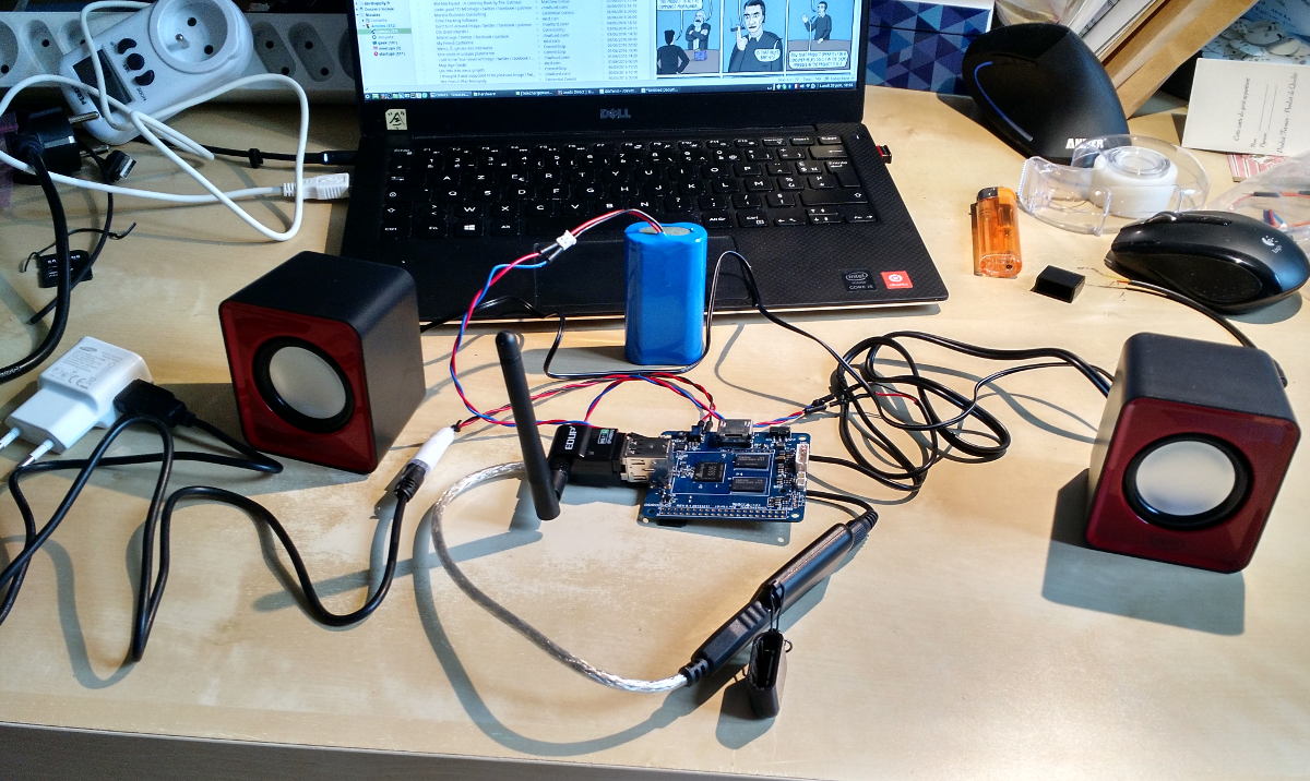
Notice the Odroid is not powered to the wall. A LiPo battery pack supplies it with electrons. The Odroid has a built-in voltage regulator and charger for LiPo batteries, which is very convenient in our situation. Two points are less practical: no built-in wifi and no analog audio out. I had to put a wifi dongle (Edup 802.11N) but it suddenly had very high latency (pings in the 800ms to the router) so I later put an old Hercules key instead, which worked fine, despite consuming almost a watt. For the audio, I had to put a USB DAC (digital to analog converter). I used here an old Creative X-Fi I had somewhere, but cheaper options exist, such as the 5HV2 chips. Surprisingly, I could not find any DAC to connect to the I2S digital audio out interface that was not more expensive that the Odroid itself. The speakers, despite costing less than 6 euros, produce a very decent sound.
Designing the user interface
Then we needed to build a user interface around this player. Screen, buttons, touchscreen, e-ink segmented displays? To keep it simple and stupid, I ordered a LCD (20 columns and 4 lines) and a bunch of push-buttons and resistors. Did you know that the chip inside the LCD belongs to the family of HD44780 compatible chips, whose original chip was designed almost 30 years ago by Hitachi?
Here is a photo of the screen displaying some text, as well as a breadboard filled with buttons and resistors. The button logic is true by default (pull-up resistors), set to false when the button is pushed, connecting to a ground wire. Note that I switched to raspberry pi A+ at that stage because I planned to use MCP23017 expanders (visible on the picture, but not connected) and some LED Charlieplexing. The software to use those expanders seemed more mature on that platform. Realizing that I had enough GPIO pins (x17) to drive the LCD (requiring only 6 pins in 4-bit interface mode) and several buttons, I later decided not to use them. The simpler, the better.
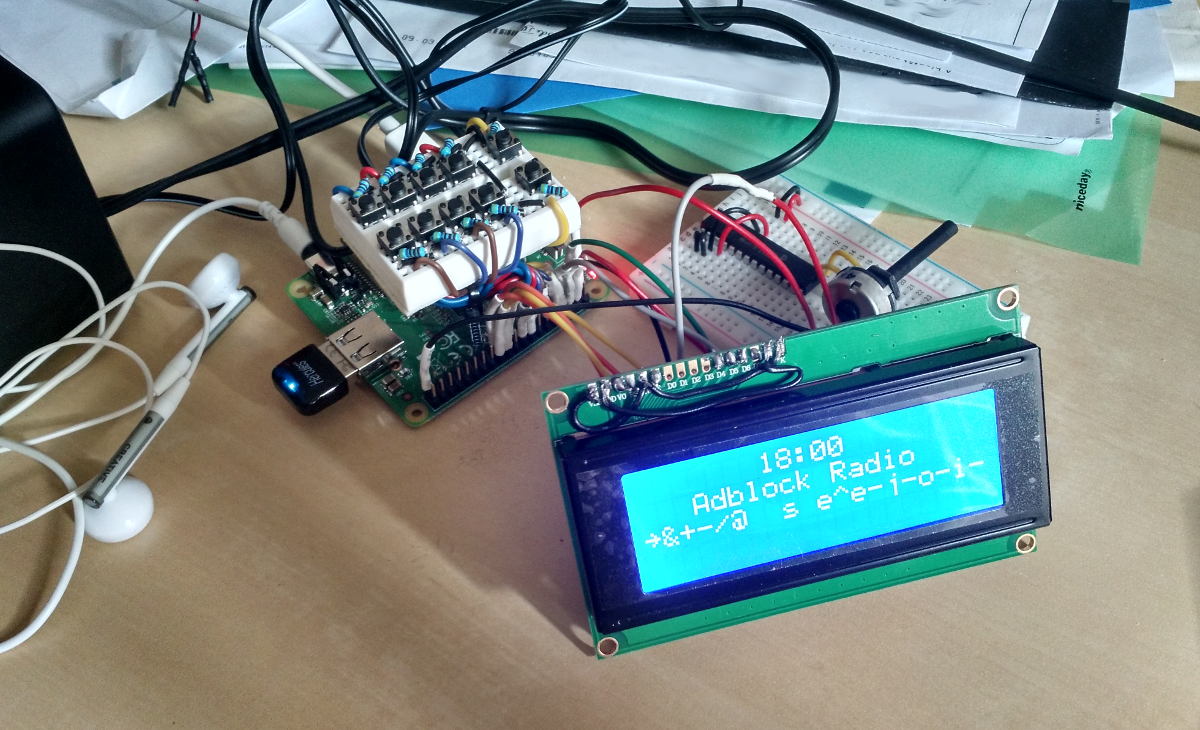
A potentiometer is used to tune the contrast on the screen. You need approximately 1.8V on the contrast pin to have the characters displayed correctly. Connecting the contrast pin to the ground (0V), 3.3V or 5V leads to unreadable text, so you need that potentiometer. You can have another one to tune the brightness of the screen. In the following shots, you will see both of them.
Note that there are ten buttons. A group of eight, plus two. The eight are bound to eight radios. You press it and the radio plays the corresponding stream. Among the two additional buttons, one is used to enable or disable ad filtering of the Adblock Radio service. The last one is used to flag any ad that would not have been detected by the filter. I should have added a on/off button, but I forgot and I did not order one in time, so the Raspberry, while supplied with power, is always on. It draws about 0.35A at 5V, so about 2 watts meaning maximum 2 euros at the end of the year. Not a big deal.
Building the case with a 3D printer
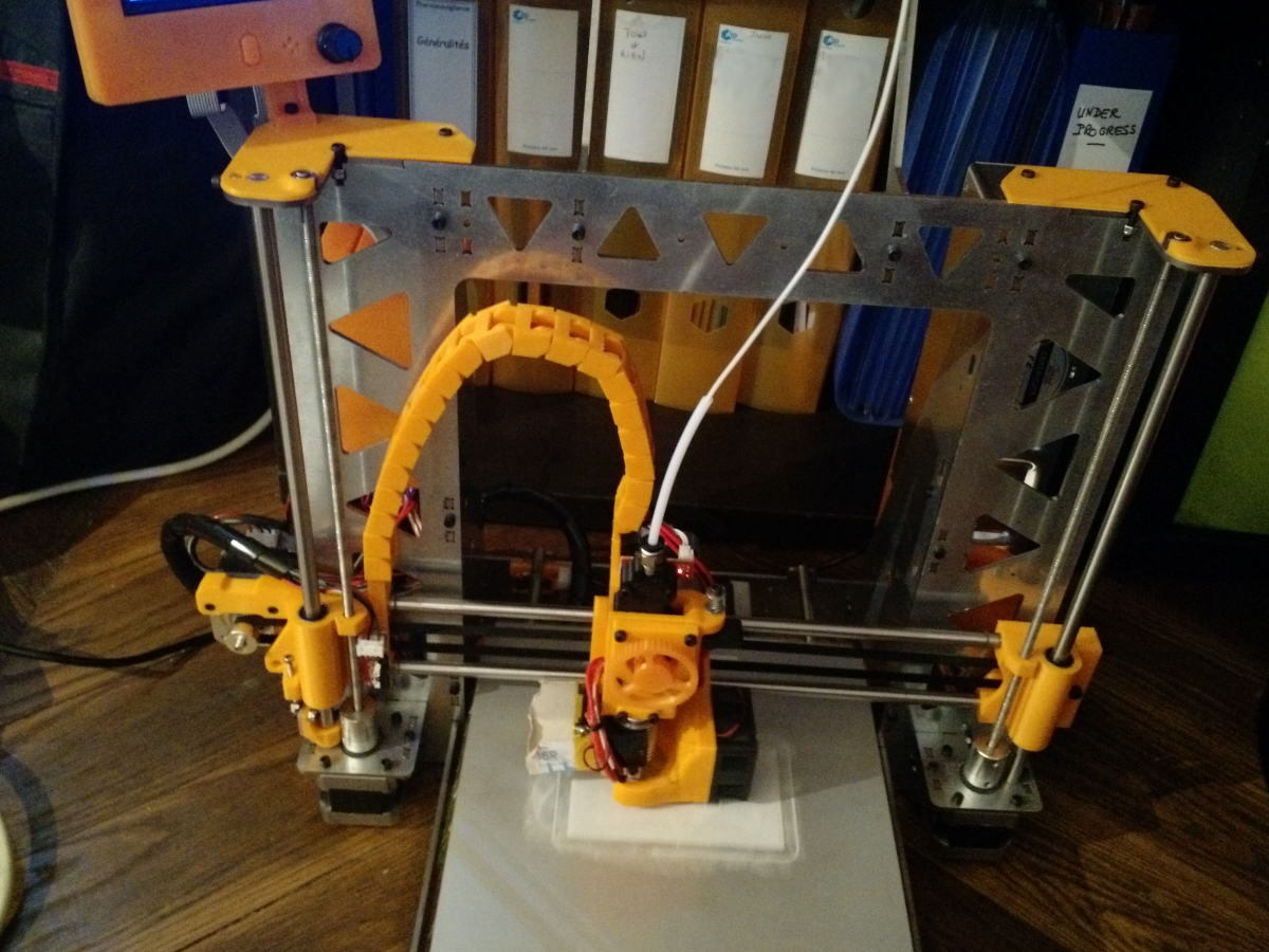
The time has come to build a box for this fantastic DIY device. I am glad to have a 3D printer close to me, a HTA3D P3Steel
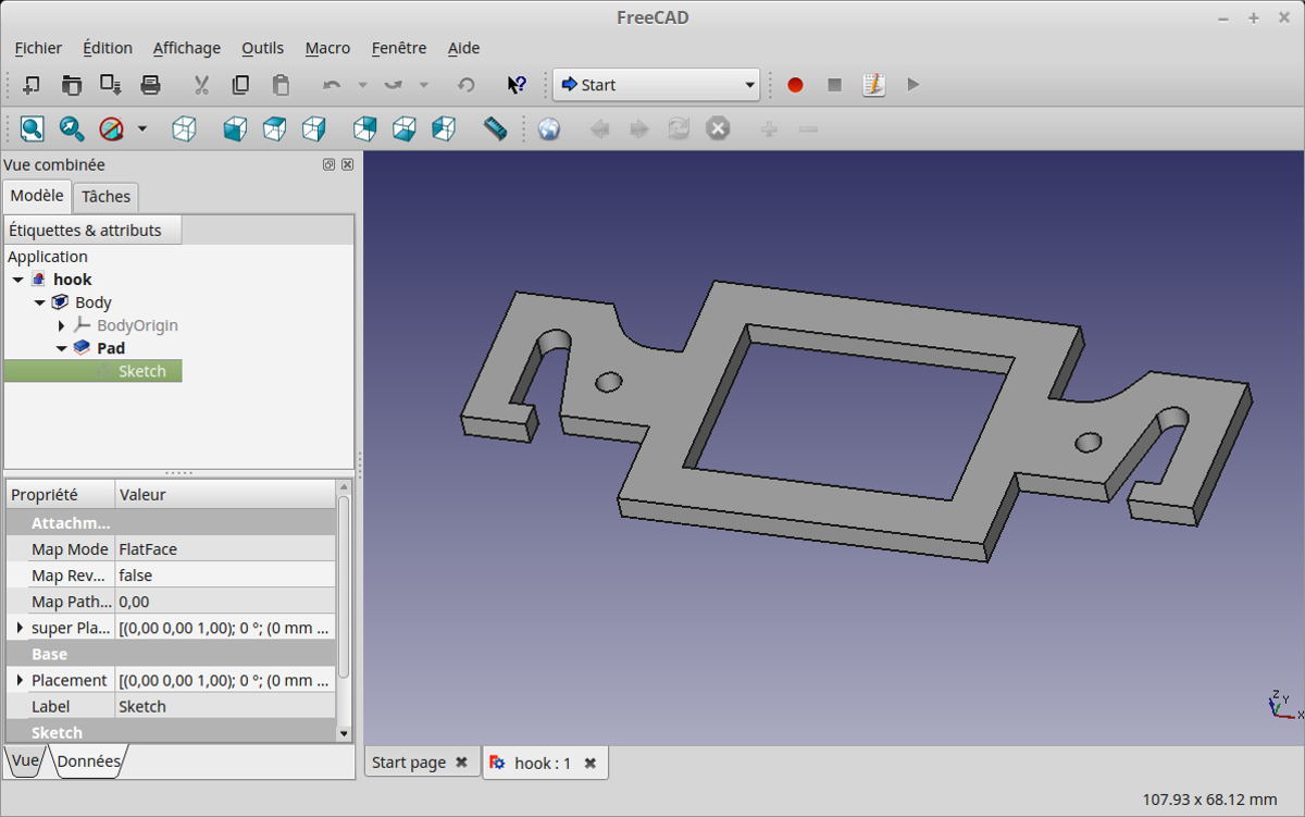
I turned on Freecad to design the pieces. It's free software (as in freedom) so it's very cool. Unfortunately, in my humble noob opinion, it is not as friendly and stable as Catia is, for example. Though it did the job fine this time.
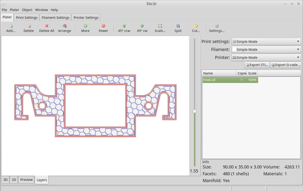
Once the 3D model of the pieces is ready, it has to be converted into 3D printer instructions, called G-code, such as the following: printer head, please go to the coordinates X,Y,Z and follow this path at velocity V by injecting this precise amount of plastic, etc.. This operation was done with the software Slic3r (read slicer, screenshot below). I was really impressed by this piece of software. The filling patterns of pieces are really great, the interface is clear, intuitive (even if very technical sometimes) and bug-free in my experience. Congratulations to the developpers of Slic3r.
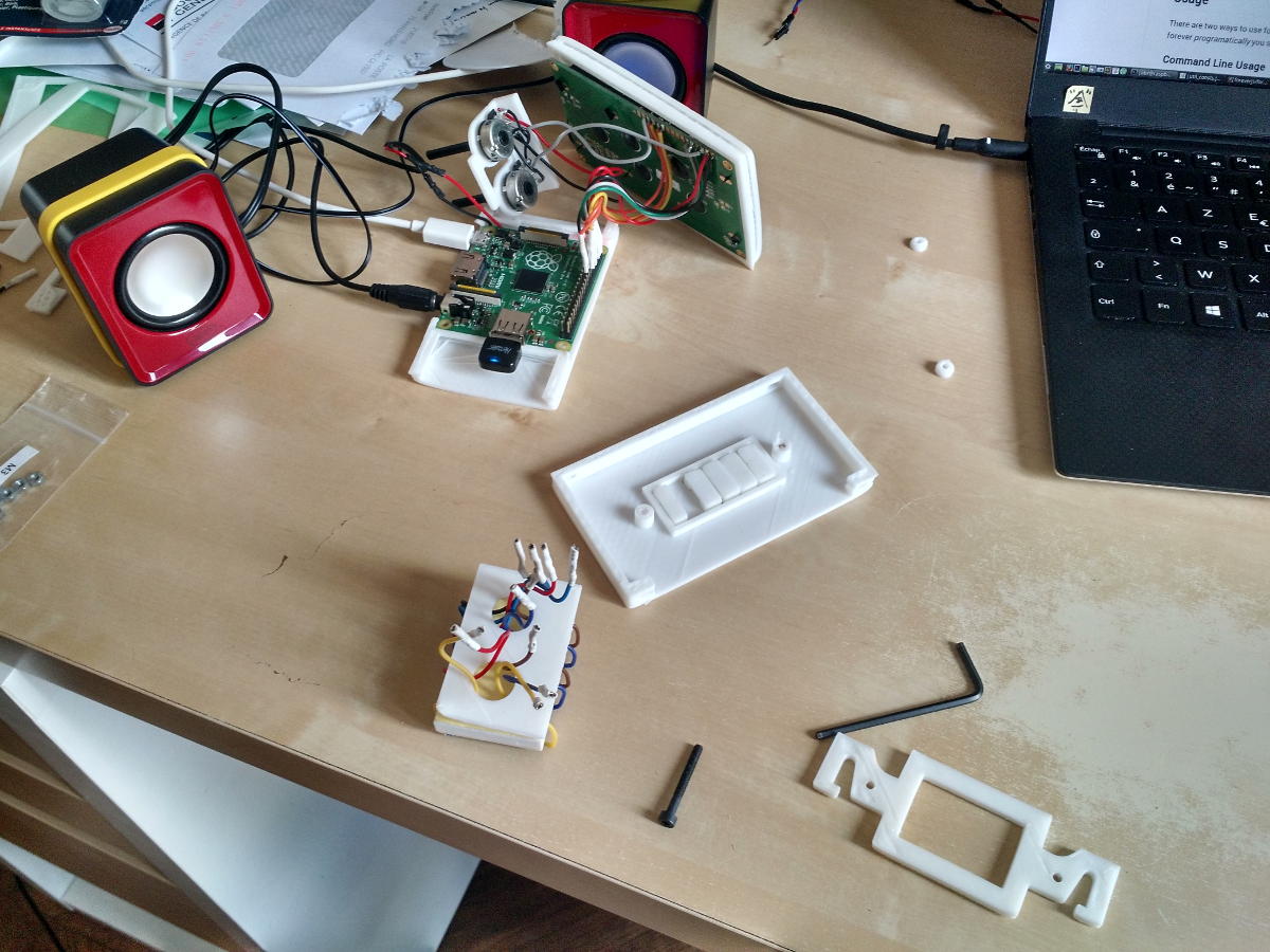
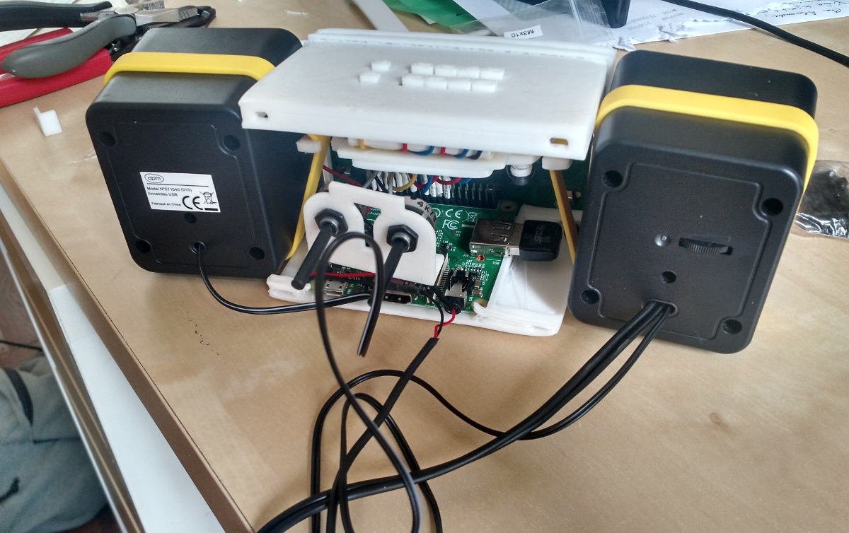
So I finally got the pieces. The buttons block will be tied with two screws between the top of the radio case and the double hook piece you saw above. The speakers will be tied with yellow rubber bands on each hook. Then simple surfaces will close the box.
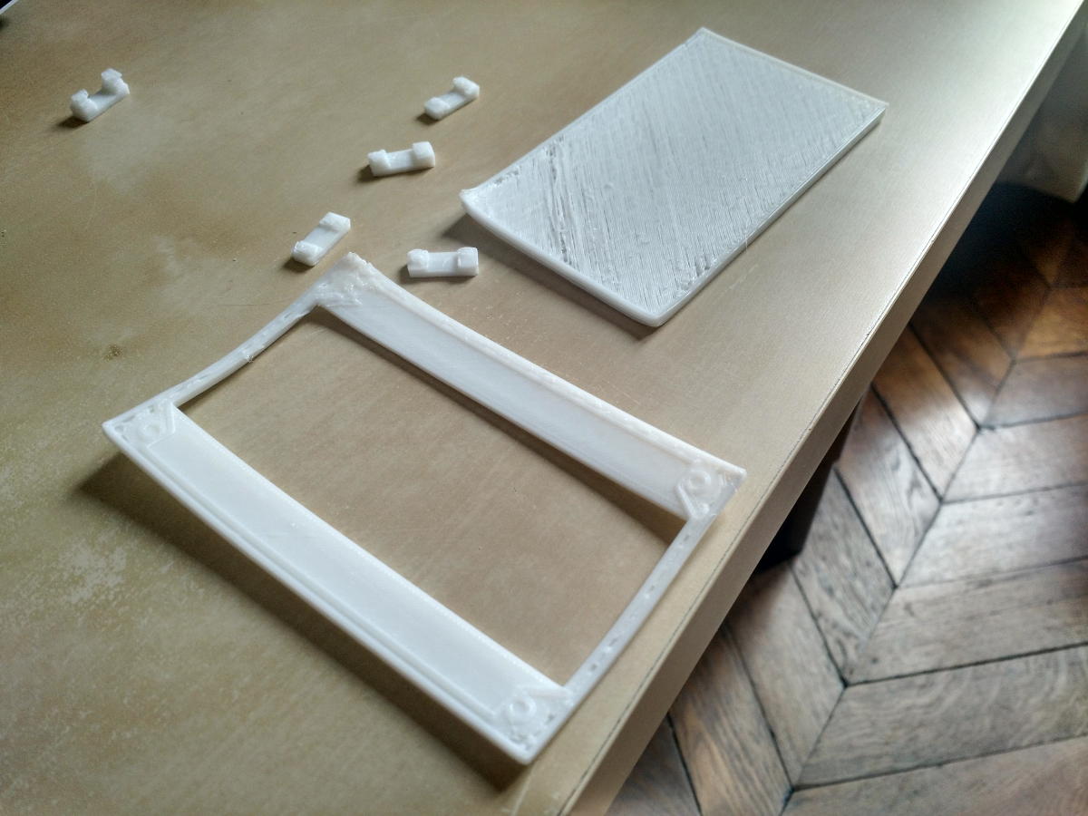
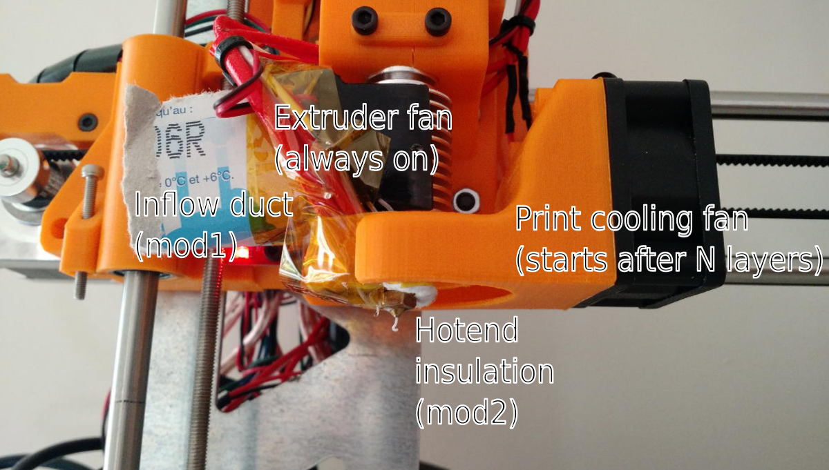
3D printing is an art that requires some trial and error at the beginning. It's not complicated but you need to invest some time to gain experience and be able to print at a decent quality. The deal is to heat the plastic (PLA in this case) at a higher temperature than the melting point, so that it melts in the hot end (heated piece of metal with a small hole from which the plastic goes out), but not too high as it has to solidify just after being placed in the printing zone. It has to cool down slowly and homogeneously, so as not to bend, crack and/or detach from the printing bed because of the internal mechanical constraints due to thermal expansion or retraction. On the printer I used, the extruder fan, used to establish a thermal equilibrium by pumping the heat deposited in the hot end, blew a little bit of air on the bottom left part of the prints, making it cool too quickly. This caused the failure of several prints, as shown on the picture below. I installed some tape and paper to direct the airflow a bit further (visible later in the close-up picture as "mod1"). I also covered the heatbed with removable glue stick, which helped the first layer of plastic stick to the heatbed. That solved the issue.
A second problem I encountered while printing is with the interaction between the hot end (hot piece of metal from where the plastic goes out) and the second fan of the extruder, the print cooling fan. It is used to to cool and harden the deposited plastic, allowing more precise prints at the scale of several centimeters - this fan is enabled only after having printed several layers so as to not bend the print, phenomenon detailed before. This is my fault: I did not install the thermal insulation for the hot end that was provided by HTA, as it was not useful when printing small elements and made the observation of the hotend more difficult. When printing the big pieces of the radio case, once turned on, it cooled down the hot end suddenly and caused a temporary jam in the extruder that lasted long enough to spoil the print. So I have installed that insulation (visible as "mod2" on the pictore below) and things were printed correctly afterwards.
The assembly is almost finished! Note that the two potentiometers in the center let the user tune the brightness and contrast of the screen. The volume level is adjusted directly on one of the speakers.
Final results
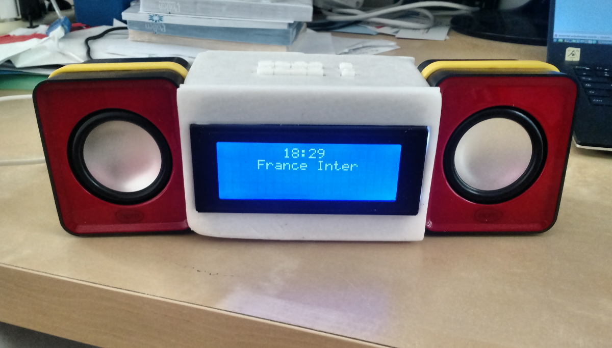
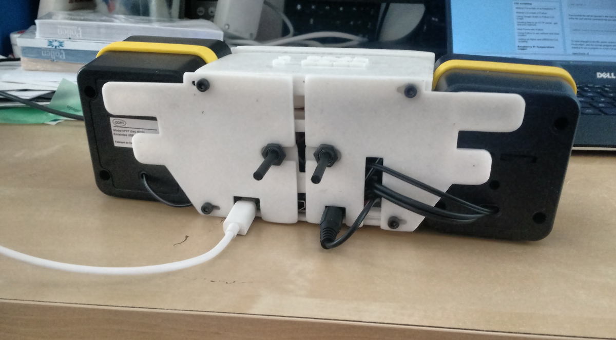
And here is the result. The two yellow rubber bands prevent the case from slipping on the table.
I offered this radio for the birthday of a close relative, who listens a lot to the radio. I think it's an original gift! This prototype lacking a on/off button, I added a few goodies to be displayed when the radio was off, that are refreshed automatically: first, the aeronautical weather reports called METARs, published by the nearest airport, as well as the hours of the next sea tides.
The wifi configuration is hardcoded in the radio, meaning it is not usable in unknown locations, unless some unpractical configuration is done. IoT companies usually alleviate this problem by publishing a companion app for smartphone that can configure the IoT device through Bluetooth. This is out of my budget… for now! Stay tuned.